Standard DIN 6888
Woodruff Keys, Dimensions and Application
|
Dimensions in mm - source DIN 6888
|
| Publication date: 08/1956 |
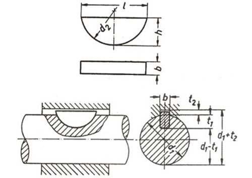
| key width b h9 |
1 |
1.5 |
2 |
2 |
2.5 |
3 |
3 |
3 |
4 |
4 |
4 |
| key heigth h12 |
1.4 |
2.6 |
2.6 |
3.7 |
3.7 |
3.7 |
5 |
6.5 |
5 |
6.5 |
7.5 |
|
for shaft diameters d1 form A
|
3÷4
|
4÷6
|
6÷8
|
6÷8
|
8÷10
|
8÷10
|
8÷10
|
-
|
10÷12
|
10÷12
|
-
|
|
for shaft diameters d1 formB
|
6÷8
|
8÷10
|
10÷12
|
10÷12
|
12÷17
|
12÷17
|
12÷17
|
12÷17
|
17÷22
|
17÷22
|
17÷22
|
| d2 |
4 |
7 |
7 |
10 |
10 |
10 |
13 |
16 |
13 |
16 |
19 |
| l ≈ |
3.82 |
6.76 |
6.76 |
9.66 |
9.66 |
9.66 |
12.65 |
15.72 |
12.65 |
15.72 |
18.57 |
| ≈ weigth in kg x1000 pcs, (ρ=7,85 kg/dm3) |
0.031 |
0.153 |
0.204 |
0.414 |
0.518 |
0.622 |
1.10 |
1.8 |
1.47 |
2.4 |
3.27 |
|
Dimensions in mm - source DIN 6888
Publication date: 08/1956
|
| key width b h9 |
5 |
5 |
5 |
6 |
6 |
6 |
6 |
8 |
8 |
8 |
10 |
10 |
10 |
| key heigth h h12 |
6.5 |
7.5 |
9 |
7.5 |
9 |
10 |
11 |
9 |
11 |
13 |
11 |
13 |
16 |
|
for shaft diameters d1 form A
|
12÷17
|
12÷17
|
-
|
17÷22
|
17÷22
|
17÷22
|
-
|
22÷30
|
22÷30
|
-
|
30÷38
|
30÷38
|
-
|
|
for shaft diameters d1 form B
|
22÷30
|
22÷30
|
22÷30
|
22÷30
|
30÷38
|
30÷38
|
30÷38
|
38 |
38 |
38 |
38 |
38 |
38 |
| d2 |
16 |
19 |
22 |
19 |
22 |
25 |
28 |
22 |
28 |
32 |
28 |
32 |
45 |
| l ≈ |
15.72 |
18.57 |
21.63 |
18.57 |
21.63 |
24.49 |
27.35 |
21.63 |
27.35 |
31.43 |
27.35 |
31.43 |
43.08 |
| ≈ weigth in kg x1000 pcs, (ρ=7,85 kg/dm3) |
3.01 |
4.09 |
5.73 |
4.91 |
6.88 |
8.64 |
10.6 |
9.17 |
14.1 |
19.3 |
17.6 |
24.1 |
39.9 |
Standard ISO 3912
Woodruff keys and keyways
The norm applys to cylindrical shafts and shafts ends, and gives the relationship which should be observed between the diameter of shaft and the section of key. Steel with a tensile strength of 590 N/mm is defined as the material to be used.
|
Dimensions in mm - source ISO 3912
Publication date: 06/1977
|
| b nom max |
1 |
1.5 |
2 |
2 |
2.5 |
3 |
3 |
4 |
4 |
|
b min
|
0.975 |
1.475 |
1.975 |
1.975 |
2.475 |
2.975 |
2.975 |
3.97 |
3.97 |
| d2 min |
3.88 |
6.85 |
6.85 |
9.85 |
9.85 |
12.82 |
15.82 |
15.82 |
18.79 |
| d 2 max |
4 |
7 |
7 |
10 |
10 |
13 |
16 |
16 |
19 |
| h min |
1.34 |
2.54 |
2.54 |
3.625 |
3.625 |
4.925 |
6.41 |
6.41 |
7.41 |
| h max) |
1.4 |
2.6 |
2.6 |
3.7 |
3.7 |
5 |
6.5 |
6.5 |
7.5 |
|
Dimensions in mm - source ISO 3912
Publication date: 06/1977
|
| b nom max |
5 |
5 |
5 |
6 |
6 |
8 |
10 |
|
b min
|
4.97 |
4.97 |
4.97 |
5.97 |
5.97 |
7.964 |
9.964 |
| d2 min |
15.82 |
18.79 |
21.79 |
21.79 |
24.79 |
27.79 |
31.75 |
| d2 max |
16 |
19 |
22 |
22 |
25 |
28 |
32 |
| h min |
6.41 |
7.41 |
8.91 |
8.91 |
9.91 |
10.89 |
12.89 |
| h max |
6.5 |
7.5 |
9 |
9 |
10 |
11 |
13 |
Standard UNI 6606
Woodruff keys. Dimensions and application.
Example and leaflet with relation to the field of application of Woodruff key (nominal dimensions, tolerances, diameter, chamfer, length) and keyway (length, depth, round-off radius). Material: steel with r greater than or equal to 590 n/mm2 in the finished state.
|
Dimensions in mm - source UNI 6606
|
| Publication date: 02/1980 |
| key width b h9 |
1.5 |
2 |
2 |
2 |
2.5 |
3 |
3 |
3 |
3 |
4 |
4 |
4 |
4 |
| key heigth h h12 |
2.6 |
2.6 |
3.7 |
5 |
3.7 |
3.7 |
5 |
6.5 |
7.5 |
5 |
6.5 |
7.5 |
9 |
|
shaft diameters d1
|
4÷6
|
6÷8
|
6÷8
|
6÷8 |
8÷10
|
8÷10
|
8÷10
|
8÷10
|
8÷10 |
10÷12
|
10÷12
|
10÷12
|
10÷12 |
| d2 |
7 |
7 |
10 |
13 |
10 |
10 |
13 |
16 |
19 |
13 |
16 |
19 |
22 |
| l ≈ |
6.76 |
6.76 |
9.66 |
12.65 |
9.66 |
9.66 |
12.65 |
15.72 |
18.57 |
12.65 |
15.72 |
18.57 |
21.63 |
|
Dimensions in mm - source UNI 6606
Publication date: 02/1980
|
| key width b h9 |
5 |
5 |
5 |
5 |
6 |
6 |
6 |
6 |
8 |
8 |
8 |
10 |
10 |
10 |
10 |
| key heigth h h12 |
6.5 |
7.5 |
9 |
10 |
9 |
10 |
11 |
13 |
11 |
13 |
15 |
13 |
15 |
16 |
17 |
|
shaft diameters d1
|
12÷17
|
12÷17
|
12÷17
|
12÷17 |
17÷22
|
17÷22
|
17÷22
|
17÷22 |
22÷30
|
22÷30
|
22÷30 |
30÷38
|
30÷38 |
30÷38
|
30÷38 |
| d2 |
16 |
19 |
22 |
25 |
22 |
25 |
28 |
32 |
28 |
32 |
38 |
32 |
38 |
45 |
55 |
| l ≈ |
15.72 |
18.57 |
21.63 |
24.49 |
21.63 |
24.49 |
27.35 |
34.43 |
27.35 |
31.43 |
37.15 |
31.43 |
37.15 |
43.08 |
50.83 |
Standard NF E22-179
Mechanical transmissions. Woodruff keys. Dimensions and tolerances.
This standard provides the dimensions and tolerances of the disk keys and the corresponding seats in the shaft and hub.
Standard BS 4235-2
Woodruff keys and keyway
This norm provides details such as the relationship to be observed between the diameter of the shaft and the section of the key for both torque transmission and positional applications.
|
Dimensions in mm - source BS 4235-2
Publication date: 10/1977
|
| b nom max |
1 |
1.5 |
2 |
2 |
2.5 |
3 |
3 |
4 |
4 |
|
b min
|
0.975 |
1.475 |
1.975 |
1.975 |
2.475 |
2.975 |
2.975 |
3.97 |
3.97 |
| d2 min |
3.88 |
6.85 |
6.85 |
9.85 |
9.85 |
12.82 |
15.82 |
15.82 |
18.79 |
| d 2 max |
4 |
7 |
7 |
10 |
10 |
13 |
16 |
16 |
19 |
| h min |
1.34 |
2.54 |
2.54 |
3.625 |
3.625 |
4.925 |
6.41 |
6.41 |
7.41 |
| h max) |
1.4 |
2.6 |
2.6 |
3.7 |
3.7 |
5 |
6.5 |
6.5 |
7.5 |
|
Dimensions in mm - source BS 4235-2
Publication date: 10/1977
|
| b nom max |
5 |
5 |
5 |
6 |
6 |
8 |
10 |
|
b min
|
4.97 |
4.97 |
4.97 |
5.97 |
5.97 |
7.964 |
9.964 |
| d2 min |
15.82 |
18.79 |
21.79 |
21.79 |
24.79 |
27.79 |
31.75 |
| d2 max |
16 |
19 |
22 |
22 |
25 |
28 |
32 |
| h min |
6.41 |
7.41 |
8.91 |
8.91 |
9.91 |
10.89 |
12.89 |
| h max |
6.5 |
7.5 |
9 |
9 |
10 |
11 |
13 |